ADDITIVE MANUFACTURING · FDM / FFF
FDM / FFF for functional thermoplastic parts
We produce functional thermoplastic parts with FDM / FFF, from design iterations and prototypes to jigs, fixtures, housings and selected production requirements. A heated nozzle deposits thermoplastic material layer by layer. Tell us what the part needs to do, and we will define the material, orientation, build and finishing approach with you.
Not sure whether FDM / FFF is the right process? Tell us about the part, quantity, working environment and intended use, and we will work through the options with you.
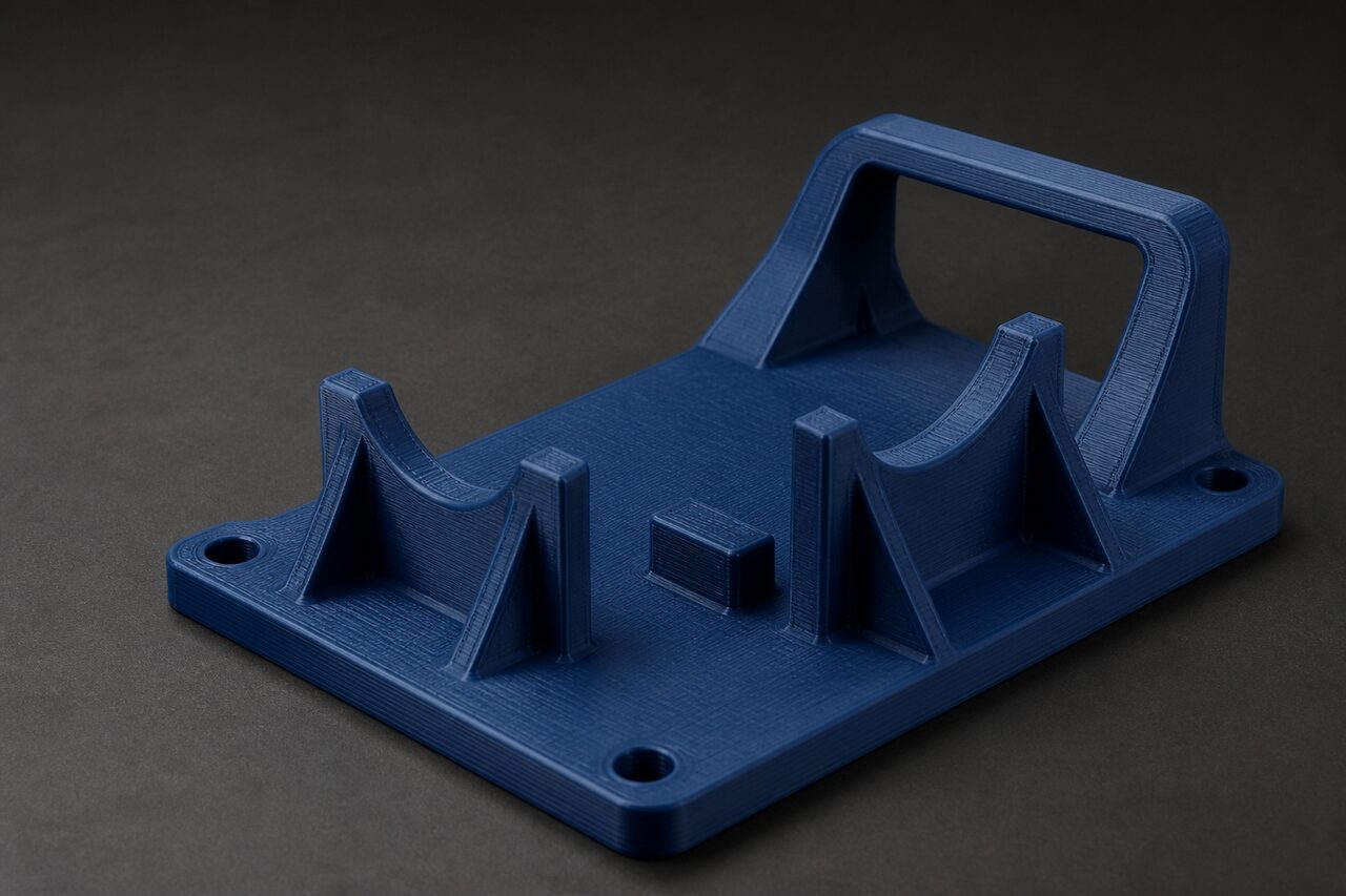
CAPABILITY OVERVIEW
FDM / FFF capability at a glance
- Material system
- Application-selected thermoplastic filament
- Production scope
- Functional prototypes, jigs, fixtures, housings and selected production requirements
- Build approach
- Heated-nozzle material extrusion, deposited layer by layer
- Surface
- Visible layer structure, with support removal and secondary finishing reviewed against the requirement
We take an FDM / FFF project from definition through production, finishing, verification and delivery. See how AtomAdd works
WHERE FDM / FFF FITS
Functional geometry, planned around orientation and use.
FDM / FFF is well suited to prototypes, manufacturing aids and functional parts where thermoplastic behaviour, geometry and practical use define the build. Orientation and deposited layer direction influence load response, support contact and surface appearance, so they are planned around critical interfaces, working loads and finish requirements.
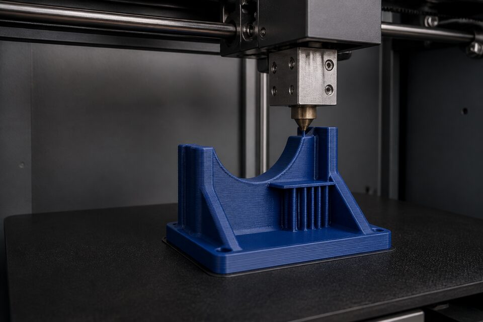
MATERIAL, BUILD & FINISH
The thermoplastic and build strategy follow the requirement.
FDM / FFF materials are selected around the part’s purpose, including stiffness, toughness, temperature exposure, chemical environment, dimensional needs, colour and appearance. We confirm the material route against the specific requirement rather than treating one filament as suitable for every part.
Orientation, perimeter strategy, internal structure and support placement are reviewed together because they influence load response, weight, surface and finishing. After printing, support removal, sanding, machining, coating, painting and assembly requirements are considered against the geometry and intended use.
If the material or finish is not yet decided, begin with the load, environment, interfaces and outcome the part must support.
START WITH WHAT YOU KNOW
What helps us evaluate an FDM / FFF part.
Begin with the job the part must perform. Loads, interfaces, environment and assembly expectations help us evaluate the material, orientation and build.
- CAD model, drawing or physical sample
- Application and intended use
- Quantity or expected repeat-production range
- Critical loads, interfaces, threads and clearances
- Temperature, chemicals, UV or outdoor exposure
- Surface, colour, finishing and assembly expectations
The material or finish can remain “Not yet decided.” Share what is available, and we will work through the production options with you.
START WITH THE REQUIREMENT
Start with what the part must do in use.
Tell us what the part must support, locate, protect or prove. We will turn that working requirement into the material, build and finishing approach and carry it through to finished parts.